Friday, October 17, 2014

Lab Report Day 15 - DC Circuits (Circuits, Series, Parallel, Resistors)

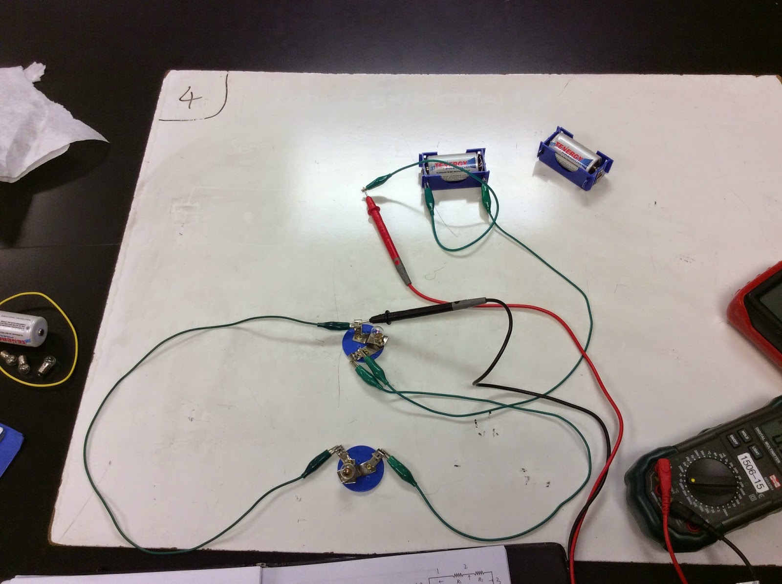
Circuits
We get two different circuit at the beginning of class.
This is the first circuit. For the first circuit, the top and the bottom bulb light up and the third is not.
 
We make assumptions that when we close the switch,  The top and bottom two bulbs will be the same bright, and the middle one will not light up. When the switch is closed, nothing changes. Our predictions is correct. The third bulb in the middle does not light up unlit because the potential difference between the junctions is zero. Or we can say that the current in the middle one comes from opposite direction, thus, they will cancel out. Since no current is on the middle bulb, it will not light up. 
 
 
IMG 0236
 
 
For the second circuit, both bulbs light up and the switch is open.
IMG 0240
 
We predict that when the switch is closed, both bulbs would stay the same. When the switch is closed, nothing happens. This is due to the potential being the same on the left and one the right. The potential at the point where the third battery joins the circuit of the other two remains the same when the switch is closed. 


Series Circuits

In this lab, we build a series circuit using one or two batteries. The current and the voltage are measured at certain points and recorded For a series circuit, we observe that the total voltages is the sum of all voltages. The sum of the voltages is equal to the voltage of the source of power (battery). The current is observed to be the same.

This is the set up.


IMG 0181Our data for voltage

Since the wire we choose are not very good, they have a very large resistance. So we measure the voltage of the wire too. And the sum of the voltage equal to the voltage of the power supply.

IMG 0182
Our data for current. They appear to be the same everywhere in a series circuit. 
 
Parallel Circuits
 
We then build a parallel circuit, and we measure and record the current and voltages at certain points. 
The set up of a parallel circuit.
IMG 0183
Data for voltage and current (we change the wires which have small resistance this time.)
Our data tells us that the voltages are almost the same everywhere in a parallel circuit. We get the conclusion that in a parallel circuit, the voltages are the same. For the current, we notice that the sum of the currents equals to the current of the power supply. 


Resistors

For this lab, we identify the resistance of a resistor by its colors. The resistance of a resistor can be expressed by AB x 10^C, which A is the first color, B is the second color, and C is the third color. The fourth color on the resistor is either gold or silver and that represents the uncertainty of the resistor. 

Professor Mason is cutting a resistor to let us see the inside of a resistor.


 What a resistor looks like inside.


We find resistance for three resistors, and use a multimeter to check the resistance to see if we get our value right.  As seen in the whiteboard, the resistances are accurate within the uncertainty. I will buy resistors from them if needed. 

 
We learn how to calculate the total resistance in a parallel circuit. We then will measure to see if it is the same as our answer.


Professor Mason is measuring the total resistance of several resistor in parallel. It is pretty close to our calculated value. It proves our theory of calculating the total resistance in parallel.

Some sample practice


Summary:
In today’s class, we learn more about parallel and series circuit. We know how to calculate the total voltage, current, resistance in different circuits. We know how to use the multimeter better.

Wednesday, October 15, 2014

Lab Report Day 14 - Electric Potential

1. Estimate the potential from a charged ring

Excel vs. Formula:

We use Excel to calculate the electric potential of a charged ring divided to 20 pieces. The charge, distance, and potential are used for calculation. The charge for each piece is diving the total charge of 2.00x10^-5 by 20. The distance for each piece is 0.3606 m from point P to the edge of the ring. The total potential is 4.99 x 10^5 V by adding potential for each of the pieces. Then we use V=∫kdq/r and get 4.99 x 10^5. The answers are very similar and as a result, instead of making an excel spreadsheet and cutting the ring into many pieces, the ring can be treated as a point charge and the potential can be solved using the formula.

Derivation of Electric Field of a ring.
 
Equal Potential Line-on the line, the electric potential is the same.


For this lab, the electric potential is measured at various points in space due to a source of electric potential difference. Observations and questions were answered on the worksheets in the pictures below.

Lab Set Up


IMG 0177

 
NewImage
Data we get from the lab (1)
 
NewImage
 
Data we get from the lab (2)
 
 
NewImage
Graph of Voltage vs. Postion


IMG 0179
Questions about the Lab (1) 
IMG 0180
Questions about the Lab (2)
 
Summary
In today’s class, we learn electric potential, and we learn how to derive the electric field of a non-point object. We learn what an equal potential line is. We use Excel to prove that our derivation of equations of electric potential are valid. 

Saturday, October 11, 2014

Lab Report Day 13 - Dim Bulbs and Bright Bulbs, Ohm's Law


Dim and Bright Bulbs
At first, we need to set up two different circuits, using two approximately bulbs, two approximately batteries and wires. One we need to have a dim light and the other one need to have a bright light. In this case, we can consider the bulbs as resistors.  
We make some predictions on how to make the bulb as bright (or dim) as possible. We use some symbols to represent the battery (power supply), bulb, which makes the drawing easier and easier for people to understand.

We find that in order to have a dim light, two light bulbs need to be in series and two batteries need to be in parallel, it will give the dimmest light. When we connect two batteries in parallels, the electric potential difference (voltage) does not change. However, the capacity is doubled. When we connect the two bulbs in parallels, the total resistance is less than any one of the two bulbs. It results in a larger current which makes the bulbs brighter.
In order to have a brightest light, two lights bulbs need to be in parallel and two batteries need to in series, it will give the brightest light. When we connect two batteries in series, the electric potential difference (voltage) is doubled, while the capacity is not changing. When two bulbs are connected in series, the total resistance is the addition of the two bulbs, which is bigger than any one of the two bulbs. It results in a smaller current which make the bulbs dimmer. 


Ohm’s Law


In this part of the lab, we are going to heat up the water in a water cup by putting a coil which is powered by a power supply. We are going to use LoggerPro to collect data. We can know the temperature and time from LoggerPro.


Using the voltage, current, and time, we can calculate the amount of energy put into water.
As seen in the following picture, the energy was calculated to be 24.1 kJ. Using the calculated energy and the energy equation Q=mcΔT, the theoretical final temperature is calculated to be about 53.2ºC.
However, the experimental final temperature is 42.1ºC. It is because the current and voltage keep changing during the 10 minutes period when data is being gathered.
From the derivation of Ohm’s law, we get that V=IRo + IRoα (VIt/mc). When α is small, the second half of the equation goes to 0 and we get the general form V=IR. By using the temperatures, voltages and currents from LoggerPro, we calculate the final resistance R to be 9.18 Ω. Relating resistance calculations with change in temperature, alpha, a constant value unique to different types of materials, is calculated to be 4.6*10^-4.
  
Derivation of the potential difference of a point charge.


Summary:
In today’s class, we learn the difference of a parallel and series circuit. We learn a more advanced version of Ohm’s Law. We know that resistance can change with temperature too.  

Wednesday, October 8, 2014

Lab Report Day 12 - Lighting a Bulb, Charge Detector, Ammeter, Ohm's Law

1. Light a Bulb
In the beginning of the class, we watch a video of MIT engineering students being asked to make a bulb light using a battery, a wire, and a bulb. They all cannot do it. We then use a battery, a bulb, and a piece of wire to try to make the light bulb. We were then asked to do the same. 


We have four different situations, which two of them work and the other two do not. We get a conclusion that in order to make a bulb to light, we need a power supply/battery, having current flow, a closed circuit, not too high resistance, and a conductor . The bulb lights up when the bottom of the bulb touches the battery or the wire, like the left two pictures. In the right two pictures, the bottom of the bulb is not touching. 

We are then asked to use two batteries and we can see that it produced a light that was twice as bright. We just need to double the power supply. We put two battery in series which makes the voltage of it doubled. The two time difference in current flow results in the bulb twice brighter.
We analyze how the energy works when lighting up a bulb.

We define the different in electric potential to be voltage, and the flow rate to be the current. 
We now have the equation for power. 

2. Charge Detector
1
This is what a charge detector looks like. Using the charge detector and a couple other materials, Professor Mason show us how the charge detector works.
[VIdeo 184]
First, Professor Mason rubs a balloon with his head and brings it near the charge detector and the light goes to yellow. What the red light tells us is that there is a negative potential near by and when the positively charged balloon is brought in, it can be seen in the video below that the light changes from red to yellow.
NewImage
Afterwards, Professor Mason takes a battery and brings in the positive end of the battery to the charge detector and the light remains red. Because the light did not change, it is clear that the charge detector was not detecting any charge at all. This tells us that the overall charge of the battery is zero.


3. Ammeter


At first, we find that the current in a series circuit is the same for everywhere.
An ammeter can measure the current in a circuit. It measures the current flowing through different parts of a simple circuit . First we created a simple circuit and the current is above 200mA. After measuring each part of the circuit, we noticed that the current remained roughly the same, around 200mA. No matter where each object was, the current remained the same. This proves that in a series circuit, the current is the same for everywhere.


We derive the unit for charges. 

4. Ohm's Law

In order to do Ohm’s Law Lab, we need power supply, current meter, coil, power supply for set up.


In this part of the lab, the circuit has a voltmeter and current meter and a resistor. We then apply varying currents and changing the voltage across the coiled resistor.
By using LoggerPro, from graph of V vs. I, it shows a perfect linear relationship between current and voltage. It makes sense because when we have a constant , V=IR. V is proportional to I. It proves the direct relationship between volt and current with equation V=IR.


With the linear relationship from voltage and current, we get an equation y=mx+b which y is the voltage (electric potential). b is initial potential, x is the current. m, which is the slope is the ratio of voltage over current, is the resistance.  From the graph, we can know that the Resistance of this wire is about 7.26 Ω.

NewImage
Since we find the relation between V, I, R to be R=V/I, we are going to determine how the thickness of a wire could affect the resistance. 
NewImage
The set up to see how thickness of a wire affect the resistance of a wire.
NewImage
We get 4 different wires.

The circuit is hooked up to different wires with different thicknesses. The slopes of the graphs (V against I) become smaller when the wire becomes thicker. The smaller slope means that the resistance is less. Since a thicker wire allow more electrons to pass through with a bigger cross section area, the resistance of the wire will be smaller.

NewImage
From the equation, R=ρ*L/A.  Resistance is related to the resistivity of different materials, the length of the wire, the area of the cross area. From the table above, we can tell that the resistivity varies with different materials.

Summary:
In today’s class,  we learn how to build a close circuit which a bulb can light up with only one wire, one battery, and one light bulb. We also know that when the electric potential (voltage) is doubled, the bulb will be twice lighter. We learn how to use a charge detector and how to use an ammeter to detect the current. We learn the relationship between P(power), I(current), and V(voltage) to be P=VI. At last, we learn Ohm’s Law, V=IR.