Circuits
We get two different circuit at the beginning of class.
This is the first circuit. For the first circuit, the top and the bottom bulb light up and the third is not.
We make assumptions that when we close the switch, The top and bottom two bulbs will be the same bright, and the middle one will not light up. When the switch is closed, nothing changes. Our predictions is correct. The third bulb in the middle does not light up unlit because the potential difference between the junctions is zero. Or we can say that the current in the middle one comes from opposite direction, thus, they will cancel out. Since no current is on the middle bulb, it will not light up.
For the second circuit, both bulbs light up and the switch is open.
We predict that when the switch is closed, both bulbs would stay the same. When the switch is closed, nothing happens. This is due to the potential being the same on the left and one the right. The potential at the point where the third battery joins the circuit of the other two remains the same when the switch is closed.
Series Circuits
In this lab, we build a series circuit using one or two batteries. The current and the voltage are measured at certain points and recorded For a series circuit, we observe that the total voltages is the sum of all voltages. The sum of the voltages is equal to the voltage of the source of power (battery). The current is observed to be the same.

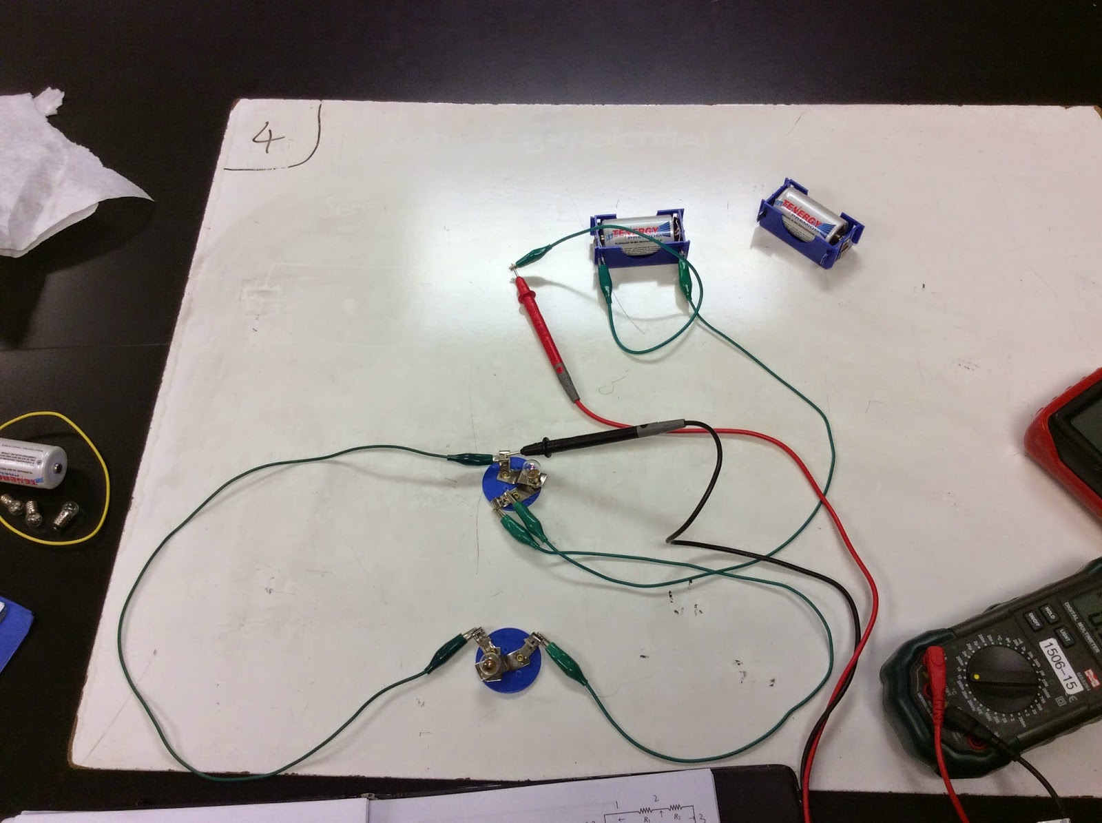
This is the set up.
 Our data for voltage
Since the wire we choose are not very good, they have a very large resistance. So we measure the voltage of the wire too. And the sum of the voltage equal to the voltage of the power supply.
Our data for current. They appear to be the same everywhere in a series circuit.
Parallel Circuits
We then build a parallel circuit, and we measure and record the current and voltages at certain points.
The set up of a parallel circuit.
Data for voltage and current (we change the wires which have small resistance this time.)
Our data tells us that the voltages are almost the same everywhere in a parallel circuit. We get the conclusion that in a parallel circuit, the voltages are the same. For the current, we notice that the sum of the currents equals to the current of the power supply.
Resistors
For this lab, we identify the resistance of a resistor by its colors. The resistance of a resistor can be expressed by AB x 10^C, which A is the first color, B is the second color, and C is the third color. The fourth color on the resistor is either gold or silver and that represents the uncertainty of the resistor.

Professor Mason is cutting a resistor to let us see the inside of a resistor.
What a resistor looks like inside.
We find resistance for three resistors, and use a multimeter to check the resistance to see if we get our value right. As seen in the whiteboard, the resistances are accurate within the uncertainty. I will buy resistors from them if needed.
We learn how to calculate the total resistance in a parallel circuit. We then will measure to see if it is the same as our answer.

Professor Mason is measuring the total resistance of several resistor in parallel. It is pretty close to our calculated value. It proves our theory of calculating the total resistance in parallel.
Some sample practice
Summary:
In today’s class, we learn more about parallel and series circuit. We know how to calculate the total voltage, current, resistance in different circuits. We know how to use the multimeter better.


No comments:
Post a Comment